Go on very small hardware (Part 3)
Most of the examples discussed in the first and second part of this series are blinking LEDs in one or another way. It may have been interesting at first, but after a while it has become a bit boring. Let’s do something more entertaining…
…let’s light more LEDs!
WS281x LEDs
The WS281x RGB LEDs (and their clones) are very popular. You can buy them as single elements, chained into long strips or assembled into matrices, rings or other form-factors.
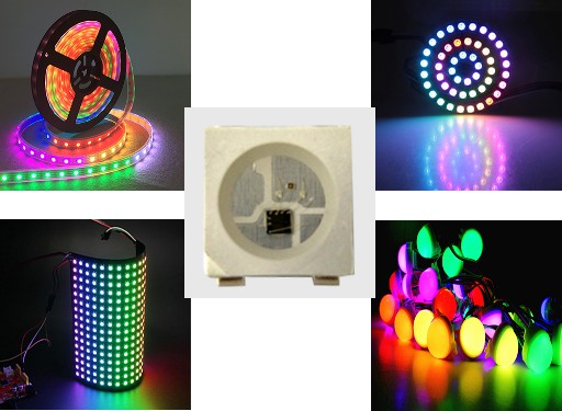
They can be connected in series and thanks to this fact, you can control a long LED strip with only single pin of your MCU. Unfortunately, the phisical protocol used by their internal controller doesn’t fit straight into any peripheral you can find in a MCU. You have to use bit-banging or use available peripherals in unusual way.
Which of the available solutions is the most efficient depends on the number of LED strips controlled at the same time. If you have to drive 4 to 16 strips the most efficient way is to use timers and DMA (don’t overlook the links at the end of Martin’s article).
If you have to control only one or two strips, use the available SPI or UART peripherals. In case of SPI you can encode only two WS281x bits in one byte sent. UART allows more dense coding thanks to clever use of the start and stop bits: 3 bits per one byte sent.
The best explanation of how the UART protocol fits into WS281x protocol I found on this site. If you don’t know Polish, here is the English translation.
The WS281x based LEDs are still the most popular but there are also SPI controlled LEDs on the market: APA102, SK9822. Three interesting articles about them: 1, 2, 3.
LED ring
There are many WS2812 based rings on the marker. I have this one:
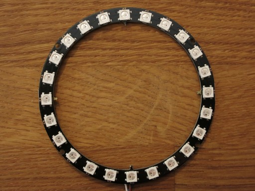
It has 24 individually addressable RGB LEDs (WS2812B) and exposes four terminals: GND, 5V, DI and DO. You can chain more rings or other WS2812 based things by connecting DI (data in) terminal to the DO (data out) terminal of the previous one.
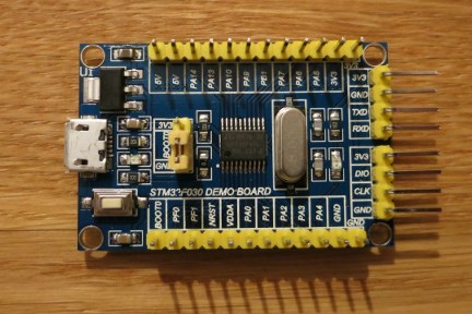
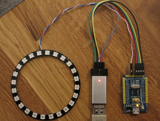
Let’s connect this ring to our STM32F030 board. We will use the UART based driver so the DI should be connected to the TXD pin on the UART header. The WS2812B LED requires a power supply with at least 3.5V. 24 LEDs can consume quite a lot of current, so during the programming/debuggin it’s best to connect the GND and 5V terminals on the ring directly to the GND and 5V pins available on ST-LINK programmer:
Our STM32F030F4P6 MCU and the whole STM32 F0, F3, F7, L4 families have one important thing that the F1, F4, L1 MCUs don’t have: it allows to invert the UART signals and therefore we can connect the ring directly to the UART TXD pin. If you don’t known that we need such inversion you probably didn’t read the article I mentioned above.
So you can’t use the popular Blue Pill or the STM32F4-DISCOVERY this way. Use their SPI peripheral or an external inverter. See the Christmas Tree Lights project as an example of UART+inverter or the WS2812 example for NUCLEO-F411RE that uses SPI.
By the way, probably the most of DISCOVERY boards have one more problem: they work with VDD = 3V instead of 3.3V. The WS281x requires at least the supply voltage * 0.7 for DI high. This is 3.5V in case of 5V supply and 3.3V in case of 4.7V you can find on the 5V pins of the DISCOVERY. As you can see, even in our case the first LED works 0.2V below spec. In case of DISCOVERY it will work 0.3V bellow spec if powered 4.7V and 0.5V bellow spec if powered 5V.
Let’s finish this lengthy introduction and go to the code:
package main

import (
	"delay"
	"math/rand"
	"rtos"

	"led"
	"led/ws281x/wsuart"

	"stm32/hal/dma"
	"stm32/hal/gpio"
	"stm32/hal/irq"
	"stm32/hal/system"
	"stm32/hal/system/timer/systick"
	"stm32/hal/usart"
)

var tts *usart.Driver

func init() {
	system.SetupPLL(8, 1, 48/8)
	systick.Setup(2e6)

	gpio.A.EnableClock(true)
	tx := gpio.A.Pin(9)

	tx.Setup(&gpio.Config{Mode: gpio.Alt})
	tx.SetAltFunc(gpio.USART1_AF1)

	d := dma.DMA1
	d.EnableClock(true)

	tts = usart.NewDriver(usart.USART1, d.Channel(2, 0), nil, nil)
	tts.Periph().EnableClock(true)
	tts.Periph().SetBaudRate(3000000000 / 1390)
	tts.Periph().SetConf2(usart.TxInv)
	tts.Periph().Enable()
	tts.EnableTx()

	rtos.IRQ(irq.USART1).Enable()
	rtos.IRQ(irq.DMA1_Channel2_3).Enable()
}

func main() {
	var rnd rand.XorShift64
	rnd.Seed(1)
	rgb := wsuart.GRB
	strip := wsuart.Make(24)
	black := rgb.Pixel(0)
	for {
		c := led.Color(rnd.Uint32()).Scale(127)
		pixel := rgb.Pixel(c)
		for i := range strip {
			strip[i] = pixel
			tts.Write(strip.Bytes())
			delay.Millisec(40)
		}
		for i := range strip {
			strip[i] = black
			tts.Write(strip.Bytes())
			delay.Millisec(20)
		}
	}
}

func ttsISR() {
	tts.ISR()
}

func ttsDMAISR() {
	tts.TxDMAISR()
}

//c:__attribute__((section(".ISRs")))
var ISRs = [...]func(){
	irq.USART1:          ttsISR,
	irq.DMA1_Channel2_3: ttsDMAISR,
}
The import section
The new things in the import section compared to the previous examples are the rand/math package and led package with its led/ws281x subtree. The led package itself contains definition of Color type. The led/ws281x/wsuart defines the ColorOrder, Pixel and Strip types.
I was wondering about using the Color or RGBA type from image/color and about defining the Strip in the way that it will implement image.Image interface but because of using a gamma correction and the big overhead of image/draw package I ended with simple:
type Color uint32
type Strip []Pixel
with a few useful methods. However, this can change in the future.
The init function
There aren’t so much novelties in the init function. The UART baud rate was changed from 115200 to 3000000000/1390 ≈ 2158273 which corresponds to 1390 nanoseconds per WS2812 bit. The TxInv bit in CR2 register is set to invert TXD signal.
The main function
The XorShift64 pseudorandom number generator is used to generate random colors. XORSHIFT is currently the only algorithm implemented by math/rand package. You have to explicitly initialize it using its Seed method with nonzero argument.
The rgb variable is of type wsuart.ColorOrder and is set to the GRB color order used by WS2812 (WS2811 uses RGB order). It’s then used to translate colors to pixels.
The wsuart.Make(24) creates initialized strip of 24 pixels. It is equivalent of:
strip := make(wsuart.Strip, 24)
strip.Clear()
The rest of the code uses random colors to draw something similar to “Please Wait…” spinner.
The strip slice acts as a framebuffer. The tts.Write(strip.Bytes()) sends the content of the framebuffer to the ring.
Interrupts
The program is ened with the code that handles interrupts, the same as in the previous UART example.
Let’s compile it and run:
$ egc
$ arm-none-eabi-size cortexm0.elf
   text	   data	    bss	    dec	    hex	filename
  14088	    240	    204	  14532	   38c4	cortexm0.elf
$ openocd -d0 -f interface/stlink.cfg -f target/stm32f0x.cfg -c 'init; program cortexm0.elf; reset run; exit'
I’ve skipped the openocd output. The video bellow shows how this program works:
Let’s do something useful…
At the beginning of the first part I’ve asked: “How low we can Go and still do something useful?”. Our MCU is actually a low-end device (8-bitters will probably disagree with me) but we haven’t done anything useful so far.
So… Let’s do something useful… Let’s make a Clock!
There are many examples of clocks built of RGB LEDs on the Internet. Let’s make our own using our little board and RGB ring. We change the previous code as described below.
The import section
Remove the math/rand package and add stm32/hal/exti.
Global variables
Add two new global variables: btn and btnev:
var (
	tts   *usart.Driver
	btn   gpio.Pin
	btnev rtos.EventFlag
)
They will be used to handle the “button” that will be used to set our clock. Our board has no button except reset, but somehow we can manage without it.
The init function
Add this code to the init function:
btn = gpio.A.Pin(4)

btn.Setup(&gpio.Config{Mode: gpio.In, Pull: gpio.PullUp})
ei := exti.Lines(btn.Mask())
ei.Connect(btn.Port())
ei.EnableFallTrig()
ei.EnableRiseTrig()
ei.EnableIRQ()

rtos.IRQ(irq.EXTI4_15).Enable()
The PA4 pin is configured as input with the internal pull-up resistor enabled. It’s connected to the onboard LED but that doesn’t hinder anything. More important is that it’s located next to the GND pin so we can use any metal object to simulate the button and set the clock. As a bonus we have additional feedback from the onboard LED.
We use the EXTI peripheral to track the PA4 state. It’s configured to generate an interrupt on any change.
The btnWait function
Define a new auxiliary function:
func btnWait(state int, deadline int64) bool {
	for btn.Load() != state {
		if !btnev.Wait(1, deadline) {
			return false // timeout
		}
		btnev.Reset(0)
	}
	delay.Millisec(50) // debouncing
	return true
}
It waits for the specified state on the “button” pin, but only until the deadline occurs. This is slightly improved polling code:
for btn.Load() != state {
	if rtos.Nanosec() >= deadline {
		// timeout
	}
}
Our btnWait function, instead of busy waiting for state or deadline, uses the btnev variable of type rtos.EventFlag to sleep until something will happen. You can of course use a channel instead of rtos.EventFlag but the latter one is much cheaper.
The main function
We need completly new main function:
func main() {
	rgb := wsuart.GRB
	strip := wsuart.Make(24)
	ds := 4 * 60 / len(strip) // Interval between LEDs (quarter-seconds).
	adjust := 0
	adjspeed := ds
	for {
		qs := int(rtos.Nanosec() / 25e7) // Quarter-seconds since reset.
		qa := qs + adjust

		qa %= 12 * 3600 * 4 // Quarter-seconds since 0:00 or 12:00.
		hi := len(strip) * qa / (12 * 3600 * 4)

		qa %= 3600 * 4 // Quarter-seconds in the current hour.
		mi := len(strip) * qa / (3600 * 4)

		qa %= 60 * 4 // Quarter-seconds in the current minute.
		si := len(strip) * qa / (60 * 4)

		hc := led.Color(0x550000)
		mc := led.Color(0x005500)
		sc := led.Color(0x000055)

		// Blend the colors if the hands of the clock overlap.
		if hi == mi {
			hc |= mc
			mc = hc
		}
		if mi == si {
			mc |= sc
			sc = mc
		}
		if si == hi {
			sc |= hc
			hc = sc
		}

		// Draw the clock and write to the ring.
		strip.Clear()
		strip[hi] = rgb.Pixel(hc)
		strip[mi] = rgb.Pixel(mc)
		strip[si] = rgb.Pixel(sc)
		tts.Write(strip.Bytes())

		// Sleep until the button pressed or the second hand should be moved.
		if btnWait(0, int64(qs+ds)*25e7) {
			adjust += adjspeed
			// Sleep until the button is released or timeout.
			if !btnWait(1, rtos.Nanosec()+100e6) {
				if adjspeed < 5*60*4 {
					adjspeed += 2 * ds
				}
				continue
			}
			adjspeed = ds
		}
	}
}
We use the rtos.Nanosec function instead of time.Now to obtain the current time. This saves much of Flash but also reduces our clock to antique device that has no idea about days, months and years and worst of all it doesn’t handle daylight saving changes.
Our ring has 24 LEDs, so the second hand can be presented with the accuracy of 2.5s. To don’t sacrifice this accuracy and get smooth operation we use quarter-second as base interval. Half-second would be enough but quarter-second is more accurate and works also well with 16 and 48 LEDs.
The red, green and blue colors are used respectively for hour, minute and second hands. This allows us to use simple logical or operation for color blending. We have the Color.Blend method that can blend arbitrary colors but we’re low of Flash so we prefer simplest possible solution.
We redraw the clock only when the second hand moved. The:
btnWait(0, int64(qs+ds)*25e7)
is waiting for exactly that moment or for the press of the button.
Every press of the button adjust the clock forward. There is an acceleration when the button is held down for some time.
Interrupts
Define new interrupt handler:
func exti4_15ISR() {
	pending := exti.Pending() & 0xFFF0
	pending.ClearPending()
	if pending&exti.Lines(btn.Mask()) != 0 {
		btnev.Signal(1)
	}
}
and add irq.EXTI4_15: exti4_15ISR, entry to the ISRs array.
This handler (or Interrupt Service Routine) handles EXTI4_15 IRQ. The Cortex-M0 CPU supports significantly fewer IRQs than its bigger brothers, so you can often see that one IRQ is shared by multiple interrupt sources. In our case one IRQ is shared by 12 EXTI lines.
The exti4_15ISR reads all pending bits and selects 12 more significant of them. Next it clears the seleced bits in EXTI and starts to handle them. In our case only bit 4 is checked. The btnev.Signal(1) causes that the btnev.Wait(1, deadline) wakes up and returns true.
You can find the complete code on Github. Let’s compile it:
$ egc
$ arm-none-eabi-size cortexm0.elf
   text    data     bss     dec     hex filename
  15960     240     216   16416    4020 cortexm0.elf
There are only 184 bytes for any iprovements. Let’s rebuild everything one more time but this time without any type and field names in typeinfo:
$ cd $HOME/emgo
$ ./clean.sh
$ cd $HOME/firstemgo
$ egc -nf -nt
$ arm-none-eabi-size cortexm0.elf
   text    data     bss     dec     hex filename
  15120     240     216   15576    3cd8 cortexm0.elf
Now, with a kilobyte of free space you can improve something. Let’s see how it works:
I don’t know how I managed to hit exactly 3:00 !?
That’s all Folks! In the part 4 (ending this series) we’ll try to display something on a LCD.